January 27, 2013 10:22 pm
Something I've been wanting to do for a while was is to build a simple analog integrator. Here is my first attempt. I bread-boarded the circuit first to get it working then make it more permanent and stable by soldering the components onto a vero board. The picture below shows the result:
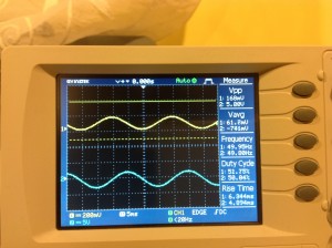
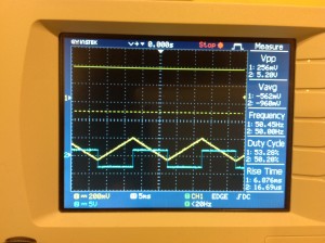
The three cables coming into the top left of the board are the +12, 0 and -12 volt power lines. The two cables coming out from the right-hand edge of the circuit board are the input and output lines (from the top) respectively. The input is fed from a function generator and the output fed to an oscilloscope. The figure below shows the result of the feeding a 50 Hz sine wave. Integration results in a cosine wave on the output. Note the two decoupling capacitors in the top left corner that despike the power lines. These are 0.1 microF capacitors.
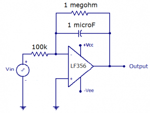
In the circuit I used a LF356 as the op amp which has a JFET input stage resulting in a very high input impedance and is typically used for precision high speed integrators. It is also quite cheap at about a dollar or less. The 1 megohm resistor across the integrator capacitor is there to avoid any unnecessary integration as a result of slight biases in the inputs when the input is supposed to be at zero.
There are a number of improvements that could be made to this circuit. The first is that any voltage bias as the inputs when both are set to zero should be removed by placing a potentiometer across the +voltage rail and the pot adjusted as appropriate. The second improvement is to add a reset button (mechanical or electronic) across the integrating capacity to reset the circuit when necessary.


No comments:
Post a Comment